This page deals with the hardware that we need to connect to the Raspberry PI in order to communicate with wireless receivers or Handsets and turn your RPI into a full functioning control center. LamPI can support several types of receiver devices for 433MHz, 868MHz or 2.4GHz which are the free bands for wireless communication in Europe. Also, several brand share almost the same protocol or work or can be made to work with minor modifications, Therefore, the list below is probably just a snapshot of a much larger list...
It is difficult to categorize devices or protocols or any other in such a way that it is easy to understand how you can interface with devices and sensors as this can be done by a direct (wired) connection to the Raspberry, over Wifi, 433MHz, Z-Wave or Zigbee. In principle every type of switch and dimmer or every type of device should be able to talk to the LamPI daemon some way or another.
The remainder of this document will be structured so that we will discuss wired connections to the Raspberry first, followed by devices/sensors that connect over 433MHz (keep in mind that these devices use some sort of transceiver or gateway connected to the Raspberry too). 868MHz and 2.4GHz follow later.
By connecting transmitter, receiver and/or sensors directly to the Raspberry, it is possible to control a great deal of devices and/or sensors. The Raspberry has 26 or 40 pins and a lot of these pins are GPIO pins and can be used to transmit or receive pulses. If connections were the only important thing here, than the Raspberry could be extended to talk to almost every device you like it to connect with.
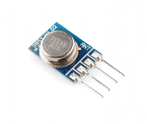
The most simple configuration is the transmitter on the picture: It uses only 3 pins: Vcc (black), Gnd (red) and a data line (yellow). Yes, I know red would be the better color for Vcc, but unfortunately the connector had its wires fixed in the wrong order :-) Later versions of the Raspberry gpio devices I made use more pin's and can receive over-the-air messages and measure temperature etc. There are all explained in separate sections.
So how can the Raspberry "talk" to all these devices:
Connect sensors and/or switches directly to the GPIO pins of the Raspberry. This seems a simple and elegant solution. However, even though it is possible to connect all sensors to the Raspberry, distance to the switches or sensor and esthetic considerations make it impossible to connect everything by wire.
Use a wireless protocol. If switches and dimmers and sensors "speak" the same wireless language, it is possible to connect one Raspberry with a transmitter/receiver pair and have them talk to your devices.
Wifi. Intelligent devices like the RaspberryPI itself can easily be connected over Wifi. However wifi may be too expensive o require too much work for simple devices. For LamPI we do not connect devices over Wifi (we could be do not at the moment).
Use 433MHz wireless communication. This protocol is on a frequency band which is free to use in a domestic area. Many home automation products use 433 MHz communication as hardware is cheap. Unfortunately there are not so many
All combinations are valid and can work.
![]()
This chapter contains information about sensor devices, transmitters and receivers that are directly by wire connected to the Raspberry. So these CAN BE 433MHz transmitters too, just to avoid confusion.
As you might expect, the list of equipment that we can interface to is long. But what hardware do we need to install in order to control all these devices? And how to connect your Weather and Energy Sensors?
 The Raspberry-PI has a 26-pins connector (called P1) to which all devices are connected, whether these are 434MHz transmitters/receivers, 1-wire sensors, I2C-bus sensors or the P1-connector of the Smart Meter in your house.
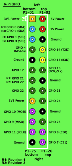
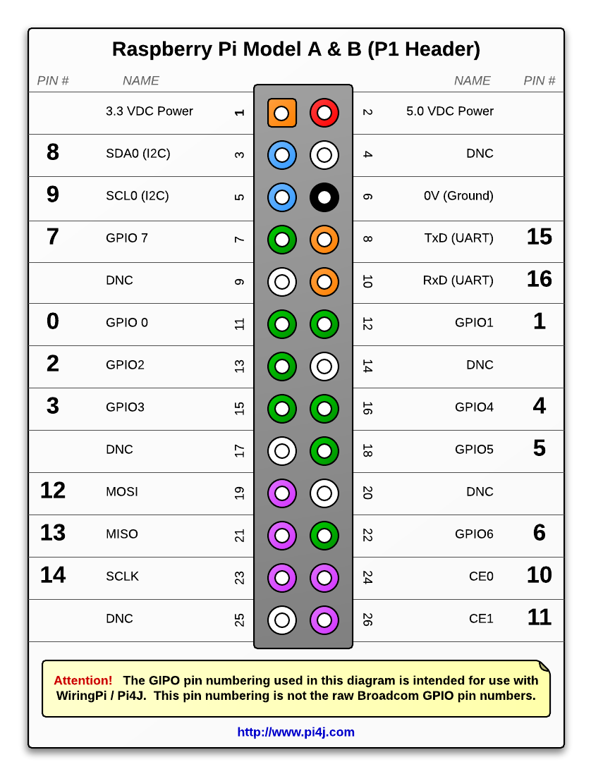
The figure on the left shows the lay-out of the RaspberryPI GPIO connector. For the 512MB version Raspberry (which is the most common version sold and in use today) use the rev 2.
If you look at the table more closely you'll notice that some sensors, transmitters or receivers use the same pins. This is for historical reasons, when I first started the LamPI project. At the moment I would make choices that ensure that we can use as many transmitters, receivers and sensors next to each other.
Note: Therefore I expect to make some changes to the default pin for the transmitter (header pin 8) as I cannot change the pin layout of the Razberry. So in a next release of LamPI it could very well be that the default pin for the LamPI transmitter will be GPIO17 or so.
| Device | Data (pin) | Vcc (pin) | Gnd |
|---|---|---|---|
| 433 MHZ Transmitter | TxD / GPIO14 (8) | 5Vdc (2,4) | yes |
| 433 MHz Receiver | GPIO18 (12) | 5Vdc (2,4) | yes |
| Razberry (868MHz Z-Wave) | GPIO14 (8), GPIO15 (10) |
||
| Dallas 1-wire bus sensors | GPIO4 (7) | 3.3 Vdc (1,17) | yes |
| I2C Bus sensors | SDA (3), SCL (5) |
3.3Vdc (1,17) | yes |
| P1 Smart Meter | -- (USB) | -- | -- |
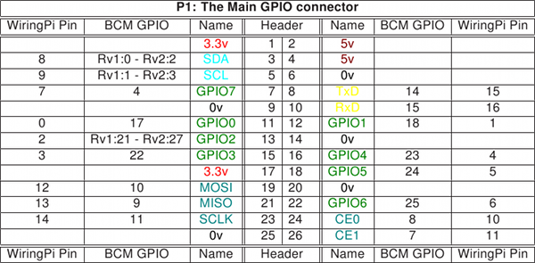
As I use the wiringPI library of Gordon, I also copied his pin-definitions which include the WiringPi numbering (being different from the GPIO pin id's). Please note that some GPIO id's used in the name column do not correspond to the general naming convention found on the internet. For example, hardware pin 12, is called either PCM_CLK or GPIO18 on most pages, but Gordon called it GPIO 01.
NOTE: As you can see in the table above, the 433 sensors in their current setup overlap with the Razberry device. This makes that both systems need to be on a separate RaspberryPI as they share pin connectors.
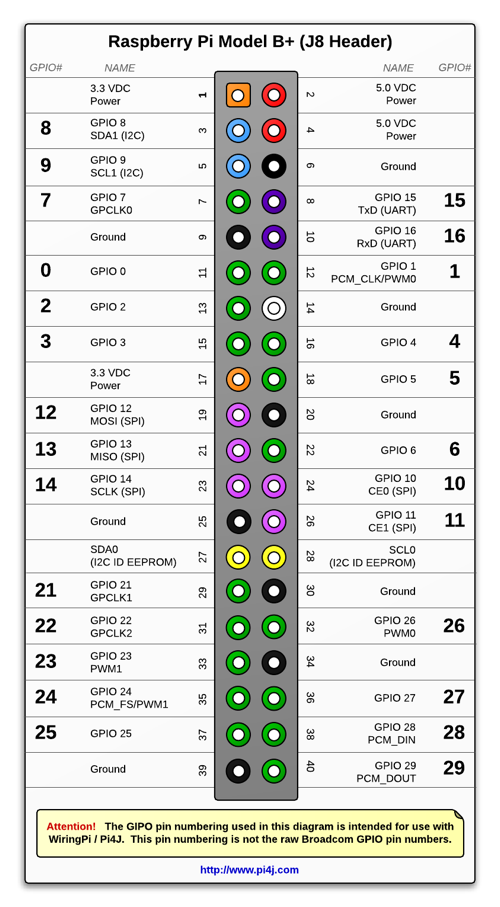
NOTE: Please forget the "BCP GPIO" columns in the figure below as this is the Broadcom numbering! LamPI uses the WiringPI description as found above.
The pin-out for the new Raspberry devices is different from the older ones. The new connector is 40-pin instead of 26-pin. Fortunately the first 26-pins are equal between all the B versions of the RaspberryPI.
Connecting weather sensors (hardware installation) is not difficult as long as their interface sticks to the more well-known I2C bus or to the Dallas (1w) bus.
There is a separate chapter on connecting sensors which you find <HERE>. The special message format used by devices to send messages to LamPI-node.js can be found <HERE>.
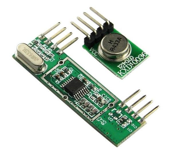
How to make the RaspberryPI a transmitter/receiver host for 433MHz? It is probably simpler than you think. Apart from the PI itself you need two really cheap small pieces of hardware, some solder and wires and a little time to put it together. So what you need are a small transmitter board and a receiver board. These boards are sold on eBay, Aliexpress and some internet shops for prices ranging from 2 $ a pair to 20$ for a receiver. In my experience, both cheap and more expensive boards work OK, if have both.
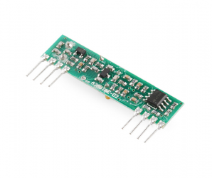
I found that most ASK/OOK based transmitters and receivers work with the 433MHz devices that are used for home automation. The protocol used by klikaanklikuit (Kaku) is OOK.
In the picture you see a receiver (L) and transmitter (R) pair that can be bought for around 2.00 $ a pair with free shipping. It is (of-course) Chinese made, and although specifications might differ from unit to unit, they work quite OK.
![]()
Frankly, I love these sets as for just 10$ I can make at least 5 prototype boards and see which one fits my PI better.
Ok, these look better than the cheap kit, and the good news is that they are better.
And the load of these super heterodyne kits so low enough that further work with low pass filters etc may not be necessary anymore. As you can see, with my setup (somewhere in 2014) the idle time is around 85% which means that the Raspberry (model 1) has plenty of time left. Obviously for this test I did not run any other functions of LamPI in order to be able to compare these results.
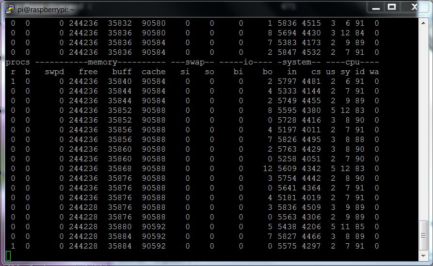
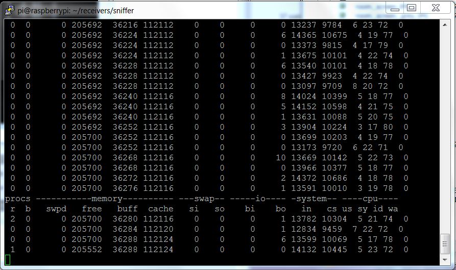
As you can see from the screendump of a terminal to one of my PIs, the load of the transmitter/receiver combo on the system (no GUI actions, only LamPI-daemon running, system receiving weather station (WT-440u) messages only) is very low. If you compare the load of this set with the cheap one above you see that it uses less than half of the cpu power that the cheap kit uses.
For your final version, where you need to rely on in your house, this may be a safe choice of transmitter/receiver.
The Dutch internet shop iPrototype also sells transmitters and receivers and their quality is very good, and comparable to the Superheterodyne set described above..
Link: https://iprototype.nl/products/components/communications/rf-transmitter-434mhz#
I bought a set of FSK (Frequency Shift Keying) transmitter/receivers as an alternative to separate transmitter/receiver sets. These work in a FSK environment only and are NOT usable for Klikaanklikuit communication. Kaku modules work with a different type of modulation, based on ASK (Amplitude-Shift Keying) or OOK (OOK is On Off Keyking, an ASK variant with 100% amplitude modulation, so on or off).
Link: http://www.hoperf.com/rf/data_link_module/HM-T.htm
Apart from separate transmitters/receivers it is also possible to work with so-called transceiver devices. These are devices that have both transmitter and receiver capabilities.
The SI4432 is a transceiver with a high sensitivity and high power. According to datasheets and articles its range is 1000-1500 meter (free sight) which is still a lot more than the average Klikaanklikuit equipment.
http://www.electrodragon.com/w/SI4432_433M-Wireless_Transceiver_Module_%281.5KM_Range,_Shield-Protected%29
We recently bought a pair of SI4432 transceivers, but as the pin grid is 1.27 mm we need a converter board first for easy soldering.
Especially the receivers can pick up quite some noise, especially in an urban area. I have been experimenting with external filters that would keep the higher-frequency crap from my receiver, and some people like those in pilight for example make an art of building a filter around those components. Thing is that with all those sensors in and around the house there is a lot of pollution which will impact the receiver. Not only will it make our received not recognize incoming messages if two transmitters send their data at the same time, it will also impact the amount of compute power needed to clearly recognize messages coming in if there is lots of noise in the air.
During my experiments I found out that with good software design the system time that these receivers use for interrupt handling can be kept close to 10-30% max, which leaves about 75% idle time that can be used for LamPI-node processing and GUI handling. I use a round buffer where pulses received by the received are stored and processed as soon as enough pulses came in to recognize a message.
Fortunately, the more expensive units work slightly better and consume less computer resources too, so I advice all of you to spend a little more money and buy the more expensive stuff
There is a separate chapter on connecting Energy Sensors with their P1 port to your Raspberry.
Please read <HERE>.
There are several ways to interface LamPI with 433MHz devices. First of all, one can connect a transmitter and/or receiver directly to the RaspberryPI. This is the cheapest solution and it is described in the previous section. Secondly, you can buy a dedicated interface such as the Rfxcomm that connects to the Raspberry over a USB interface. This device will do most if not all low-level processing for the Raspberry. And thirdly, you can make your own solution with for example an Arduino and build your own device for transmitting and receiving 433MHz messages. so what are the pro's and con's?
A direct connection to the RaspberryPI is the cheapest solution to connect (over the air) your Raspberry homeautomation solution to devices in the field. The disadvantage of using the Raspberry this way is that the RaspberryPI will spend a lot of Cpu cycles on handling interrupts of the 433MHz receiver, even if there are no useful signals received. Also, some messages are long, or have very critical timing, and the Raspberry will not receive these signals well if it has other important thing to do.
| Plus | Minus |
|---|---|
| Low Price | For devices with critical timing Raspberry is not the best I/O system |
| Support by community | Most cases of Raspberry are not designed to have a transmitter/receiver sticking out (or its antenna) |
Transmitting commands is less of an issue: Especially for transmissions to Kaku devices, the Raspberry seems to be quite capable. If one or two interrupts (with high priority) do occur, they will not influence the transmitter timing too much. The Kaku protocol is not that difficult in timing. However, for Livolo and Kopou devices that do use far shorting timing cycles, the Raspberry is not the best solution. Especially when there is lots of other work to be done by the Raspberry such as Gui handling, Daemon handling with MySQL and 433MHz receiver handling.
The rfxcomm RFXtrx433E USB 433.92MHz transceiver is the standard communication device for several commercial and non-commercial home automation solutions. It is a separate device which is connected to the Raspberry over a USB cable (which will also power it). The advantage of the Rfxcomm solution is its support of a wide range of sensors and switches that is available in the market. Also, it's manufacturer will actively integrate new devices when they become available on the market. The disadvantage of this solution: It's price is steep, 105 Euro's is more than the Raspberry and a few sensors...
| Plus | Minus |
|---|---|
| Manufacturer support | High price |
| Many devices supported | What if your specific device is not supported? |
| Works very well (hear say) |
The third option would be to combine most of the advantages of 1 and 2 and build your own 433MHz gateway.
| Plus | Minus |
|---|---|
| Low price (potential) | DIY, need to build your own supported device list |
| Better message recognition | For outside, need to find a box with room for batteries |
| Offload the Raspberry with dedicated I/O gateway |
Also, when we did all the groundwork to make such a USB-connected gateway we have the ingredients to make a standalone sensor. Every Arduino that is connected to the host with an USB connection can be a Gateway device. However, memory usage and number of pin's available to onnect to play a role here and dictate whether such Arduino is the best device to use.
For example: If you want the gateway to support every kind of sensor, detect all 433 messages and send out messages in several codecs as well, an Arduino Nano or Uno might not have enough memory and it is better to use an Arduino Mega.
But for almost every other application where the Arduino controls a few sensors and forwards their values to the gateway, Arduino Nano or Arduino Pro Mini might be very good solutions.
In its first releases, LamPI supports the first approach mainly, with support for an Arduino gateway now as a second option. The Arduino gateway does support all sensors or devices at the moment, and we will work to get more devices and sensors supported. On the other hand, some protocols are supported by Arduino Gateway or Arduino Repeater only such as the Auriol outdoor temperature sensor.
The Rfxcomm solution would probably work (after some work) quite well too, but is not tested because of the cost.
There seems to be another community project started RFlink with the same intentions as my Arduino project. http://www.nemcon.nl/blog2/2015/07/devlist.
Hardware needed to make such a node can be bought in the Nodo shop. Main disadvantage at the moment of using RFLink is that it requires an Arduino Mega. Not a big deal, but unnecessary for my use as Gateway and overkill when making an Arduino Sensor node.
Sep 2015 update: We begin to reach the end of the Nano memory capacity. The memory usage is more than 85%. So I might have to switch to the Arduino Mega type of device for the Gateway only. All sensors and repeaters will be based on Nano or Pro-Mini Arduinos which are a lot smaller. There is a Pro version of the Arduino Mega available, which is smaller and easier to use in projects, so that is where we want to look at coming period of time.
The process of unboxing the Arduino, installing the IDE and loading the first program is described HERE
Instead of connecting a transmitter and receiver directly to the Raspberry, it is equally possible to use an Arduino gateway. In this case, the Arduino will take care of all the 433 MHz wireless communication and it will connect to the Raspberry through a USB cable and port for power and host communication. For first version of the Arduino Gateway the UNO (larger footprint) and the Nano were the best candidates. In a later states we might have a look at other Arduino variants such as Nanodes, Teensy, Arduino RFu etc. should there be important advantages in using them.
I also made a version of the Arduino Gateway based on the Arduino Uno. The Uno is somewhat larger and in combination with the Arduino stick-up board Prototype Shield and a small block it is easy to make and change a setup. Functionally, the Nano and the Uno are equivalent and the code runs on both systems.So it is a matter of choice and preference.
In general, the Arduino Uno is a good starting point for your Arduino projects. Its larger size makes it easy to connect devices and sensors. However, when converting your prototypes into working production sensors in your home, the Nano might be the better choice.

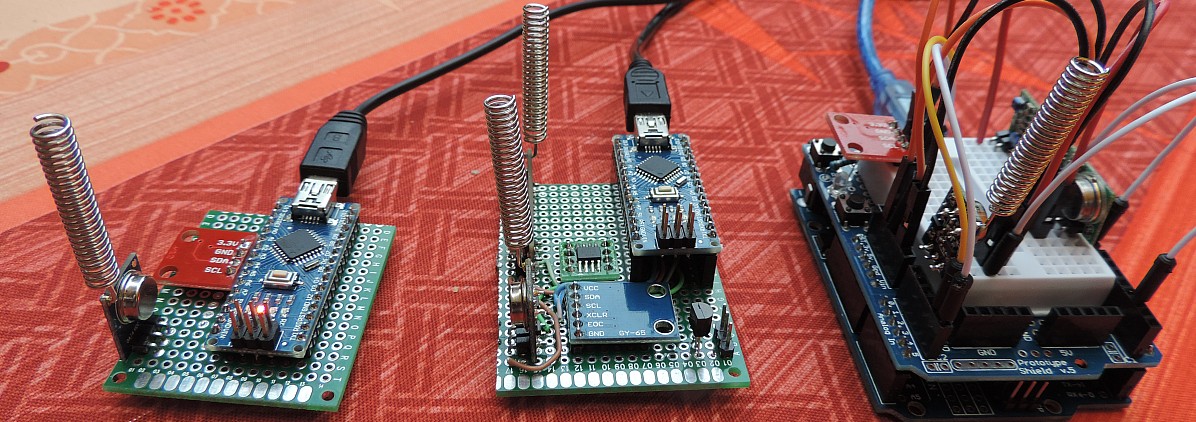
In the picture above you see the Arduino gateway (Arduin UNO with prototype board) with a transmitter and receiver (the one with the orange antenna wire). My general feeling when building this gateway was that it is too large for its purpose. The Arduino Uno has a large footprint and lots of space for experiments. But I do not need it.
That's better!
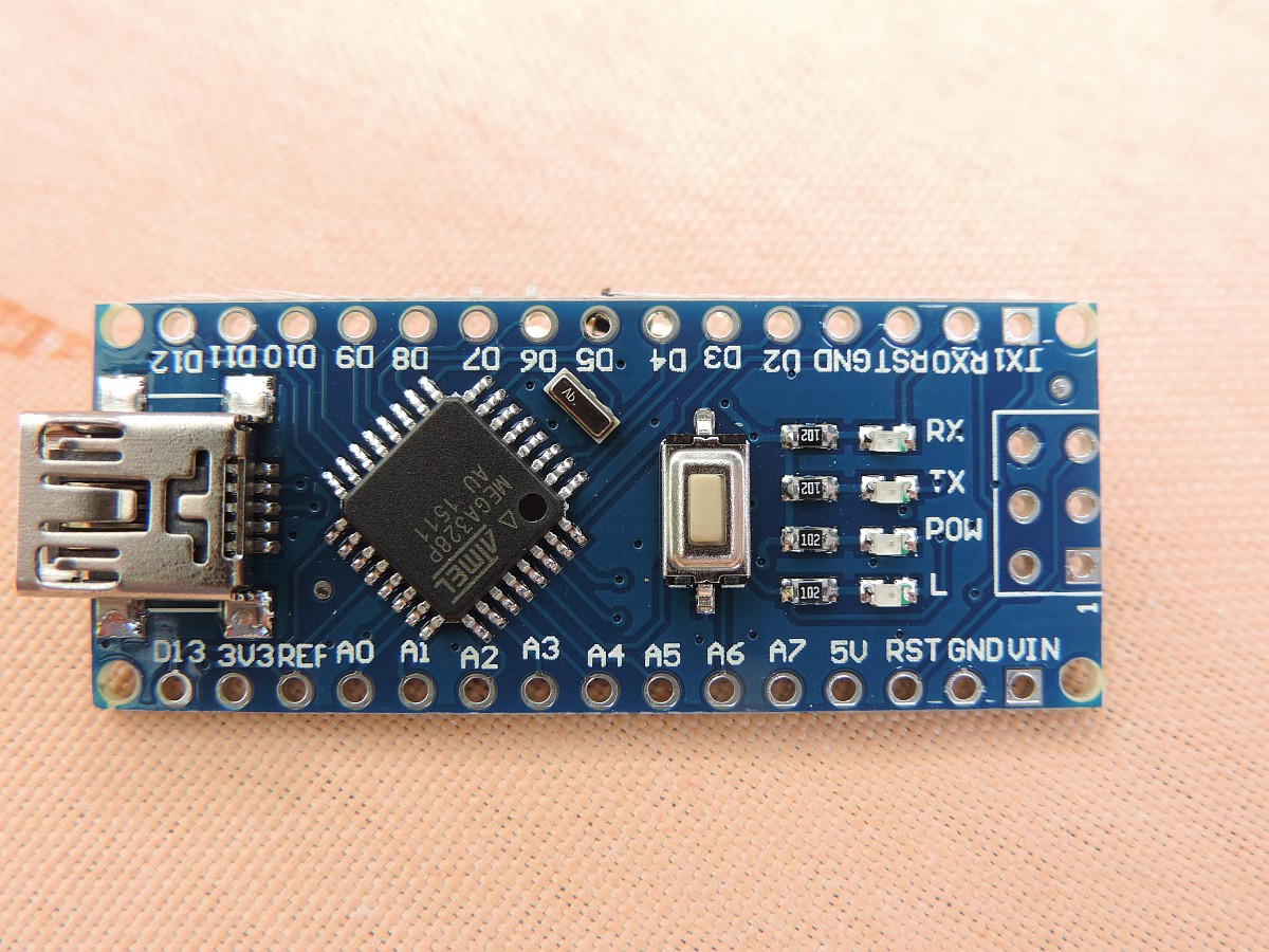
The Nano is a good system for making an Arduino Gateway device. The little machine is VERY cheap (less than EUR 2.50 including shipping) and can do all the things that the larger UNO can do as well. When it arrives at your mailbox, you just have to make a few connectors to the Arduino and it is ready for work. Its small footprint will make it difficult to give it a stable stand and therefore a small experiment board will provide that stability and offers place to connect sensors and transmitter/receiver devices as well.
 In the picture you see the Nano which is mounted on an experiment board using connectors. The transmitter is on the front, and the receiver is soldered on the rear end of the board. In the middle is a BPM085 board in the front (GY-65) and a LM75 (not connected) is found at the rear end. On the right front side is a DS18b20 device soldered (looks like a transistor), together with a 3-pin connector to attach a 1-meter water-proof sensor DS18b20.
UpdateSept 2015: I added a HTU21D sensor to the board so I am able to use this board as the main Arduino Gateway for transmit and receive but I'm also able to measu temperature, airpressure and humidity on the small footprint.
The board is used as the standard sensor/transmitter/receiver unit of one of the Raspberries in my home.
Please read more on the dedicated Arduino Gateway page
The message format exchanged between the Arduino and the Raspberry over USB is described in detail in gatewayMsgFormat
At this moment the Arduino Gateway can be used for:
A variant on the Arduino gateway is the Arduino Sensor. This is an Arduino with a temperature and/or humidity or any other sensor(s) that will forward these sensor readings over the air using a 433MHz transmitter to a Raspberry receiver.
 Earlier, when using the Raspberry to receive 433MHz messages, we would every now and then have problems with the reception of messages. The Arduino however is a much better device to receive (interrupt driven) device messages than the Raspberry itself is. Also it's form factor is smaller, its price is lower and power usage is only a fraction.
The code is in a separate branch on http://github.com/platenspeler and the Arduino must be loaded with one of the "Example" programs to make sure it behaves like an Arduino Sensor. Also, it is possible to change the address/channel combination (in the example code) so that you can build an Arduino Sensor (=WT440h device) exactly matching your home setup.
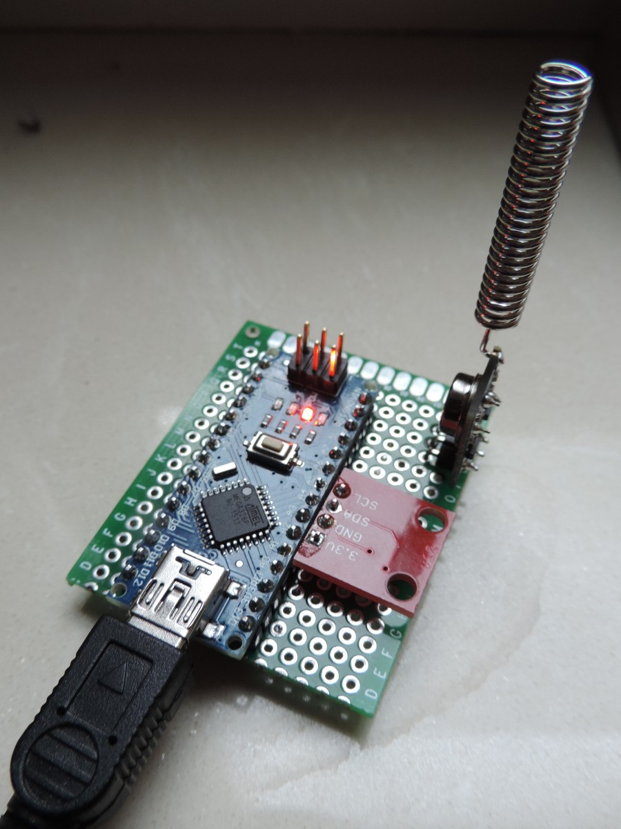
In the picture you see my setup for the Arduino Sensor. The device works great and as I programmed the Arduino to report the values coming from address 3 and channel 0. The Arduino Sensor only has 1 physical sensor connected, a HTU21 device reporting the temperature and the humidity at the spot the Arduino Sensor is locate in.
The red version of the sensor is larger than the green one, in next versions of the device I will use that green one which will save a lot of board space.
The protocol supported at the moment is the EPIC protocol that is used by the WT440h weather station. It does mean that the Arduino Sensor can behave as if it were such a WT440h device and for the receiving party it is unknown whether the messages received message is coming from a true WT440h sensor or from an Arduino Sensor device.
The WT440 protocol seems to be limited by temperature and humidity sensors, and as these weather stations are not in use so much anymore we must be looking at a better protocol, modern and supporting more devices. Alternatively we might have to build our own protocol or extend another one so that we can send any message we want over the air.
Fortunately, the solution built can easily be adapted as soon as we have another suitable transmission protocol for over-the-air messages.
Also, such a small Arduino with connectors for a few DS18B20 devices would be an excellent sensor station for temperature sensing for example for the Central Heating installation. At this moment we use a Raspberry for his purpose which is a waste of power (of the Raspberry) and energy usage as well.
For those (like me) that do not always want to power the Arduino Sensor over and USB cable, or just do not have a wall power outlet nearby, there is an alternative sensor powerd by batteries. Please have a look on the page HERE

The message format that is used to code on-board sensors over the air to a receiving Arduino Gateway is described on the page sensorMsgFormat
Wen adding a received and antenna to an existing Arduino Sensor it should also be possible to use the Arduino to build a 433MHz range extender or a repeater. Also it is possible to make a protocol conversion using this solution by building a solution with a 868MHz receiver and a 433MHz transmitter. This way, several devices in my house that are operated wirelessly using a proprietary communication protocol (not Z-Wave) can be integrated in the LamPI environment as well.
Go to the examples directory of the Arduino code and select repeater433 directory. In the Repeater433.h file it is possible to set compile-time switches that determine which protocols will be compiled into the code and recognized once the Arduino is operating.
The message format the the repeater uses to send on-board messages and received 433MHz messages to a receiving Arduino Gateway is described on the page repeaterMsgFormat.
Since there is very limited support for wired solutions, we have chosen to use the i2c protocol for LamPI when possible, and to connect several temperature sensors (waterproof) choose the 1-Wire protocol..
The message format exchanged between the Arduino Gateway and the Raspberry Host over USB is found on a separate page.
The 433Messages that go over the air are explained on this 433messaging page
If you like to get your home automation working with more sophisticated technology which enables you to query the status of your connected devices: Z-Wave is your way to go.
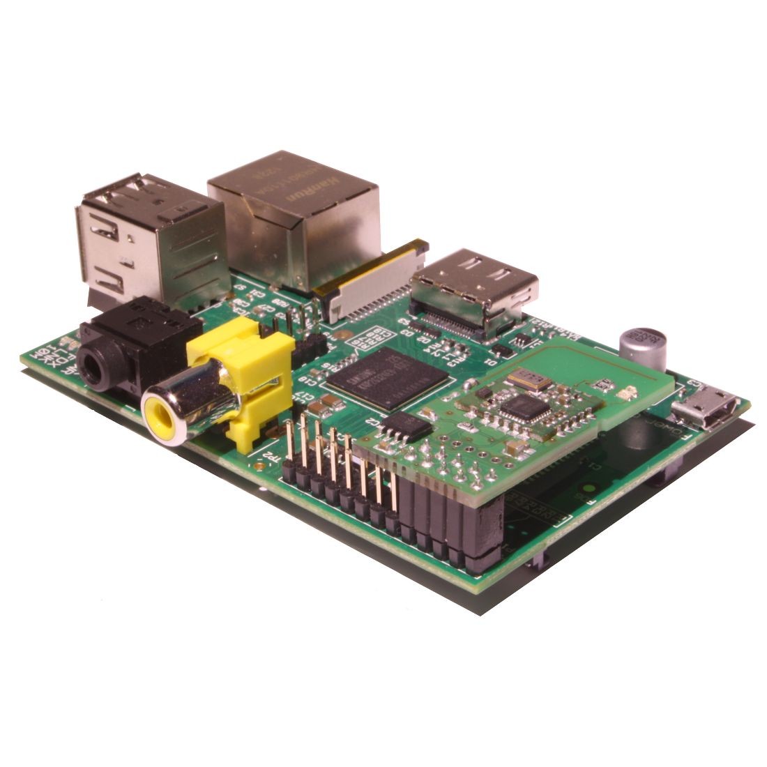
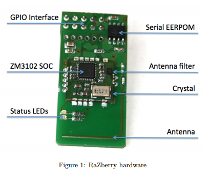
The Razberry is a small stick-on device that connect to the P1 connector of the Raspberry. It contains the firmware needed to interface with the 868MHz Z-Wave software (which the company calls ZWay). It's a little bit difficult to see in the picture above, but the Razberry is the stick-up board that is attached to the GPIO connector of the RaspberryPI model B. It uses only a few pins of the Raspberry connector, but unfortunately these are shared by most other board solutions. Therefore it is hard to make the Razberry work with traditional direct connected transmitter/receiver hardware of 2.4 GHz (Zigbee) equipment.

If you like to read more on the software for the Razberry and how LamPI interfaces with the hardware, please read further <HERE>
The Razberry Gateway is a real gateway for LamPI, that means that while LamPI can change values of the Z-Wave network devices it does not have the controlling possibilities that are needed to manage the network itself. Including (or excluding) devices in the Z-Wave network, restarting the daemon, doing firmware upgrades etc. all need to be performed by the Razberry software itself.
Once in a while the interface between LamPI and the Z-Wave computer needs resetting as some or all the functions doe not seems to work anymore. Some releases of the Razberry firmware seem to suffer more from this than others, and some even seem to randomly change values of vetwork devices. Z-wave.me, the maker of the Razberry has more focus on new features than on quality so it seems.
You can reset the gateway on the Razberry with "http://<Razberry-IP>:8083/expert" . Go to the "network" section, choose the "control" submenu and reset the API with the button.
The third protocol that is used in Home Automation environments is Zigbee. It was invented by Philips and used for its lumination solutions. However, as the protocol is difficult and is a closed and proprietary solution, not that many other vendors are using Zigbee at the moment, but their numbers increase.
I bought a module that potentially could work in a Zigbee environment, but it could very well be that I am lacking supported Zigbee devices for this solution. I will have a look shortly to see if I can make it work in the LamPI environment.
I did buy a RaspBee device from Dresden-Elektronik.de and that setup module for the Raspberry should be able to handle the Zigbee 2.4GHz traffic (like the Razberry does for Z-Wave)
For the moment Zigbee devices are on the (wish-) list of being supported
Apart from the Zigbee protocol, there are other possibilities to use the free 2.4GHz band for home automation use.