The first catagory to describe is the group of sensors that do not use a bus system to connect to the Raspberry PI (so have multiple sensors in series connected to the same wire). Instead every sensor will need to be connected separately to VCC and GND as well as be assigned its own exclusive GPIO pin.
This may or may not be sufficient for your use, but there is an advantage to this approach: These sensors in general are cheap and contain good value. There is however a drawback when using these devices (as will be explained in further details below): If we connect these sensors to a busy system the timing of the system might not be good enough to support the critical timing (in 20uSec) that these devices need.
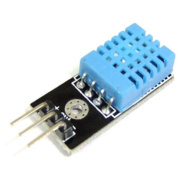
The DHT11 temperature/humidity sensor is a typical example of such a sensor device. It has 3 outside connector pins: GND, VCC and Data. Of course the latter will be the most important pin to work with. In case of the DHT11 we need to send a start pulse to the data pin, wait a predefined number of micro seconds and then we will receive the 40-bit (5 bytes) sensor reading from the device as 2 bytes humidity reading, 2 bytes temperature reading. And 1 byte for parity check.
Connecting the DHT11 is easy, it is low cost and easy to connect. However, you are advised to buy the slightly more expensive DHT22 model instead. The DHT11 does not output decimal parts of the temperature and humidity (decimal part of the output bytes are always 0). The DHT22 is fully compatible with the DHT11 but will provide temperature readings with 0.1 degree Celsius precision.
The DHT11 is not compatible with the Dallas 1-wire bus protocol (see below) which makes it a less flexible choice, even with its low pricetag.
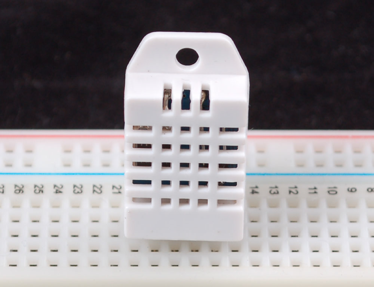
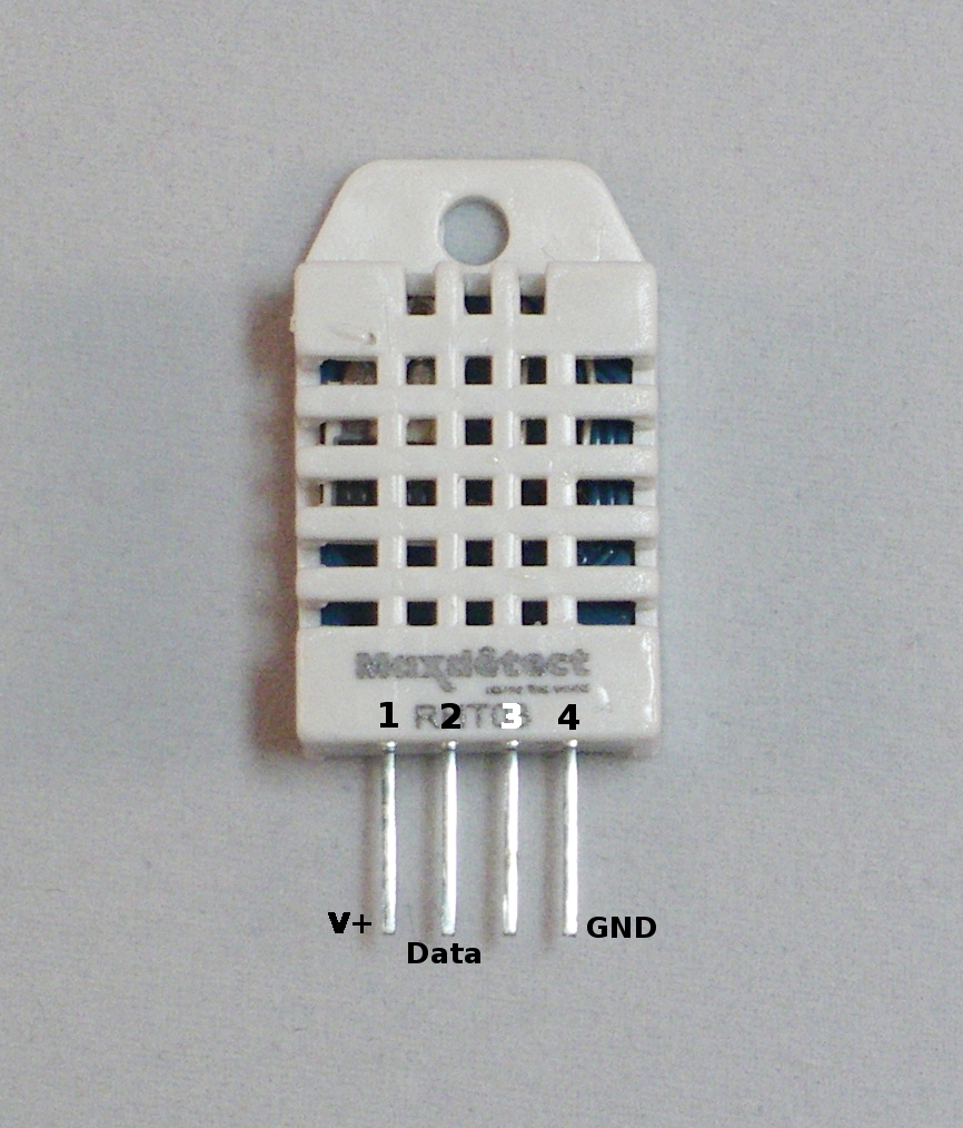
After using the DHT11 for a few days I decided to buy a DHT22 sensor. The reason was that I cannot use a sensor with a 1 degree temperature resolutions. Both are pin compatible, yet the DHT22 is more accurate. My DHT22 came with 4 pins instead of 3. The difference here is that since only 3 pins are really used that some DHT11 and DHT22 devices come with a supporting 2.54mm pin interface and are already soldered on a supporting board. If you receive a 4-pin version keep in mind that pin 3 is nc (not connected).
Writing a software program to read the temperature and humidity values from a sensor is a relatively simple task. In case of the DHT11 one needs to send a pulse sequence over the data pin which tells the sensor to send its data, wait a predefined number of microseconds and the sensor will take over the data line and starts sending its 40 bits of data.
In principle, all you have to do is read the status of the data line in uSec time intervals and as soon as the data line switches from high to low, or vice versa, note the pulse time. Every bit transmitted starts with 50uSecs High value followed by a pulse of 25 uSec means a 0 value or a pulse of around 70 uSecs which means a logical 1.
There are a few methods for reading one-wire sensors:
The first method described above is a brute-force method: we read the value/level of the data pin every uSec in loop and as soon as the sensor changes state/value we record the time interval since the last state change. This might consume an undesired amount of CPU resources. But there is a more important reason why the simple read might not work: If you use other sensors or wireless devices that use interrupt handlers to read incoming messages, your reads will not be timed correctly as these interrupts are handled with a higher priority than other running processes.
As an alternative, it is possible to use an interrupt handler to measure and time signal transitions on the data pin. The time difference between 2 transitions will be an indicator of “0” or “1” values. My experience with the last method is mixed: The method works much better when there is a lot of other data to read. But the timing of the data line is still critical and the sensor pulses are really short, even for the RaspberryPI. Especially when other interrupts arrive (433 MHz data for example) it is possible that a transition is not noticed and timing of two pulses is combined (and there is one pulse time less in the buffer).
Of course it is possible to NOT connect any 433MHz receivers to the Raspberry, in which case a single sensor can be read quite reliably. However, in our Home Automation application 433MHz receivers are key. And sad-but-true, there is a HUGE amount of 433 MHz noise in and around the home which causes lots of meaningless interrupts to the application. There are good and better (more selective) receivers, and some have developed a low-pass filter for 433MHz receivers. However, when weather station start with theirs 60-second data bursts the amount of interrupts on the receiver pin is enormous (leading to 20-30% cpu usage).
The third method is easy on the programmer. There are two functions available in the wiringPI dev library that support the Max functions: readRHT03() and maxDetectRead(). In some situations I found these functions to lock-up the Raspberry system (looking into this), whereas in other situations they work very reliable.
I did some tests with my DHT11 sensor to measure the performance of the three methods. I tested method 2 and 3 in two ways: (a) Without any other (major) load on the RPI, and (b) with the LamPI-receiver process running, so that all other 433MHz receiver interrupts needed to be dealt with as well.
For every method tested I made sure that we raised the interrupt priority prior to reading a value, and dropped it to 0 again after an successful read. This is done as reading a sensor is a synchronous operation (as seen by the initiating LamPI daemon) and we wait it to be successful and as short as possible (time). Compared to 433MHz interrupts that are generated by the receiver as a result of a remote sending a value. These asynchronous and autonome transmissions are handled by the daemon and if we miss one of those we'll pick up the next transmission.
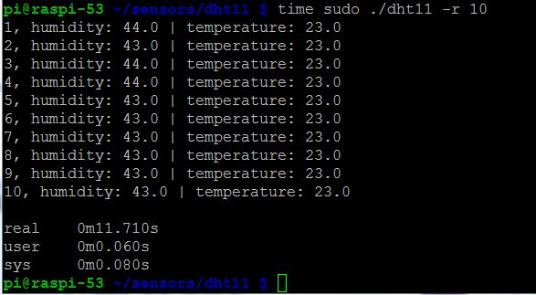
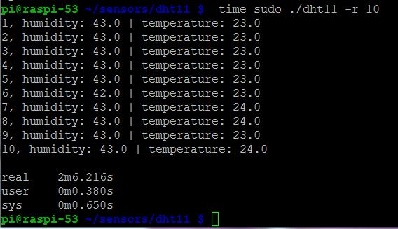

As you can see in the results above, an average successful read in a system without load takes about 3 seconds (including a 500 ms start delay between read attempts and some other short wait times)
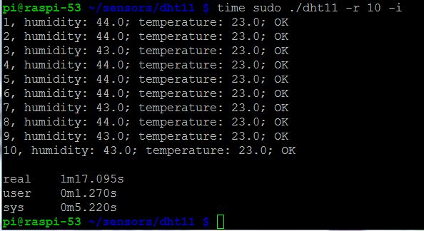
The figure above tells us that for reading 10 successful values we have a total elapsed time of 1 minute and 17 seconds, which means that a successful read takes 7.7 second on average. Still this figure is a little misleading: Not every read attempt is successful, and in the program we wait 500 milliseconds between attempts. This is because the datasheet mentions a mandatory time delay of about 1 second between read attempts. It is possible to leave out his wait, this will cause no major problems, other than that reads become less accurate (probably because the sensor cannot auto adjust between read attempts).
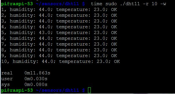
As you can see, the built-in function in the wiringPi library is highly efficient in an unloaded sitution.
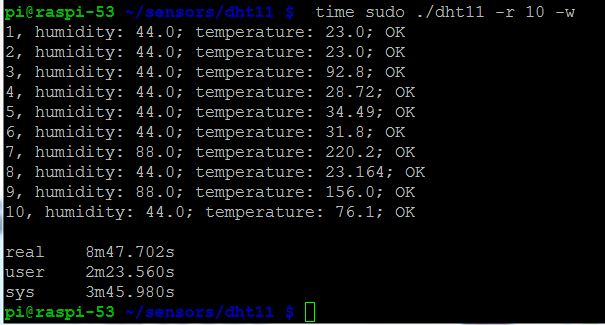
And the built-in function is very much inefficient if the system is handling regular 433MHz receiver interrupts. Also errors are introduced (even with checksum) that make its results unreliable. In practice this means that the wiringPi library function has to redo an enormous amount of read attempts that did not pass the checksum test.
For reasons described above, a non-bus interface may not always be the best solution for connecting sensors. Timing issues are already an issue when having one sensor connected to one GPIO pin, let alone when we would like to have multiple sensors connected to our Raspberry.
Therefore, I will further experiment with other 1-wire (Dallas) and 2-wire sensor (I2C) bus interconnects. Read more below.