This page describes how to make a LamPI sensor node with just a few basic components: An Arduino Pro Mini (3.3V version), a 433MHz transmitter, a sensor and a battery holder (and a soldering ion, a board and some other small stuff). The following connections must be made:
After building 3 generations of sensors that are powered over USB, it was time to build a sensor working on standard AA alkaline batteries. And of course we want an extended battery life of about one year (and longer if possible). As the Arduino nano contains several unnecessary parts that consume power in an embedded application, we will work with an Arduino Pro-Mini. This Arduino does not have an on-board FTDI serial interface, and that's fine as we only need it for programming the board.
Also it comes in both a 5.0 and 3.3V version, the latter would make it suitable for battery operation. Well, if only it would be so simple. And if there would only be ONE method to tune your Arduino Pro Mini into a battery-operated-ready system. Unfortunately, there are many versions of the same board available and there is more than one way to transform a standard Arduino ready for battery operation.
Even the 3.3V board does have a voltage regulator on board and a LED. Sometimes the LED consumes sevearl mA of power and the voltage regulator just a few uA. But the last Arduino boards I receiver it is the other way around. The LED is an efficient type (200 uA) and the voltage regulator uses 4 mA even when using low power library functions.
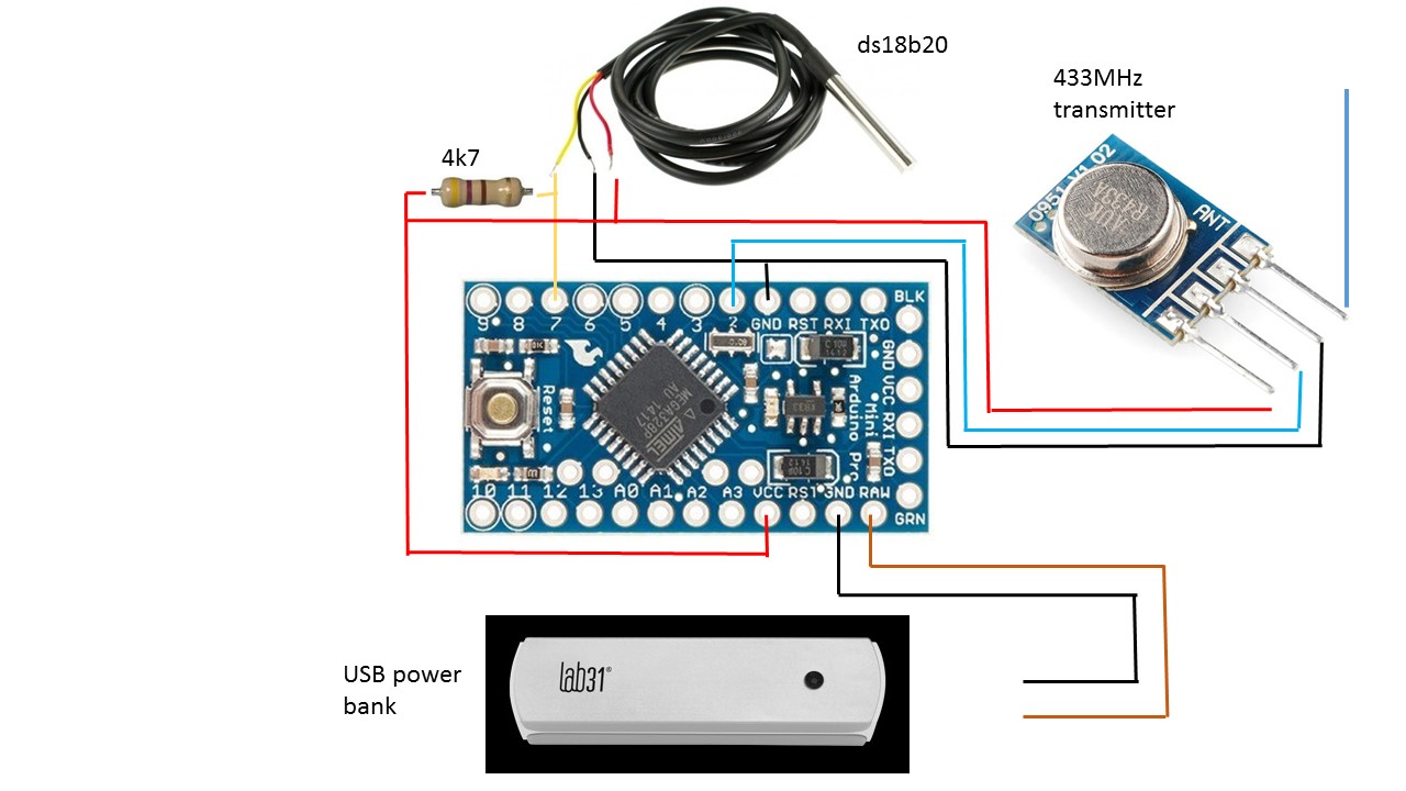
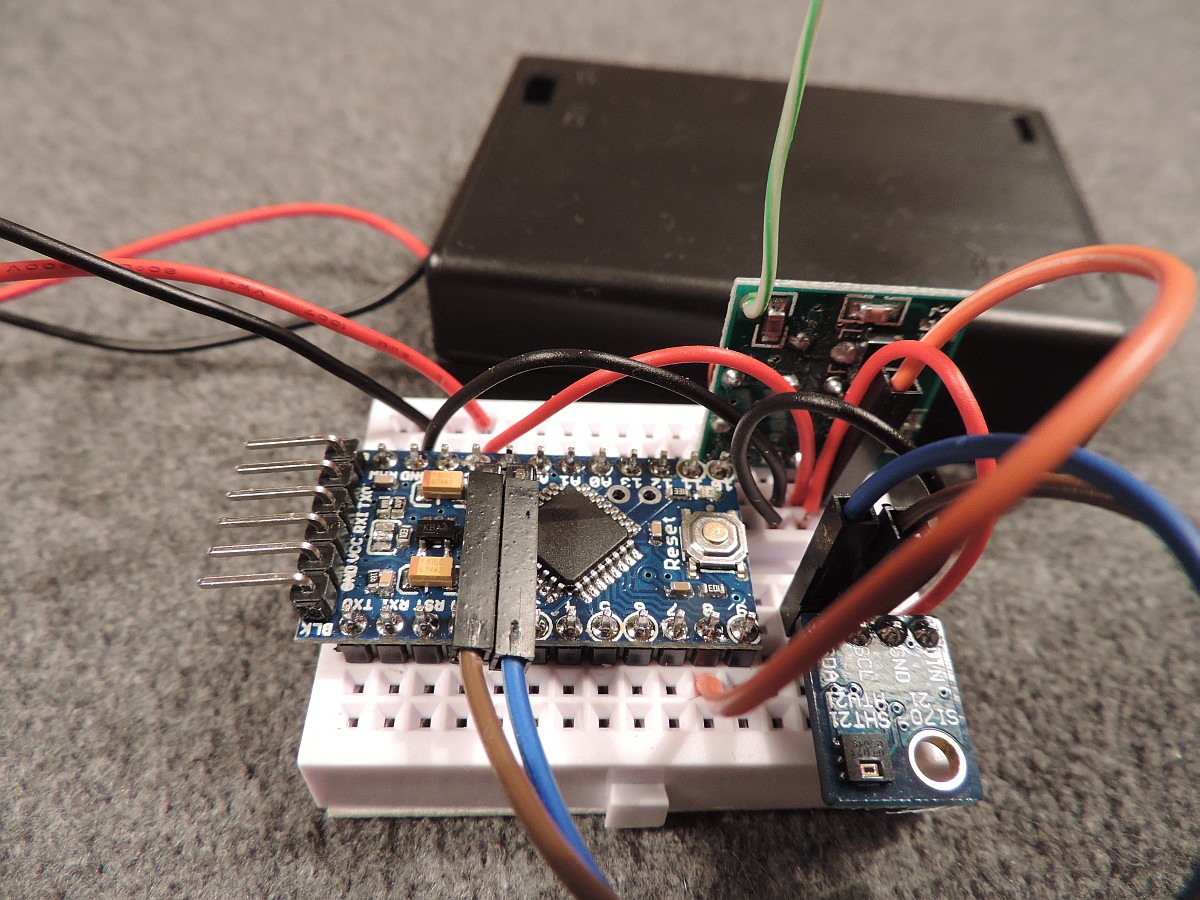
The picture below shows how to connect your sensor, transmitter and Arduino Pro Mini together.
be careful, the pin out for the transmitter might differ for your transmitter. Please look careful to the transmitter PCB which will indicate which connections should be made. Also, the data sheet for that particular transmitter will shed some light on this subject.
And, although this picture is correct, further in this text we'll explain why the power supply MUST be in range of 3.2 to 4.5 Volts and why we then will connect the power of the battery to pin VCC and NOT to RAW.
The battery shown in the back is a 2000 mA version used for mobile phones. I also experimented with a 3 x AA battery box which gives slightly more than 4.5Vdc and can be connected to the Vcc pin of the Arduino Pro-Mini directly. As the 3 x AA battery package can be connected to the Arduino Vcc pin directly (and the power bank cannot) the 3 x AA battery package may be the better option, especially if the battery life extends to several months.
Version 4 was designed to be a low-power version. The Arduino Sensor node will only power one or two sensor devices and once every minute report these values to the central gateway. For such purposes we should NOT need a high-power device. So I chose the Arduino Pro Mini node on 3.3V, which would because of its lower power and lower clockspeed work on batteries for an extended amount of time.
As an option: We could use NRF24L01 transceivers which operate on 3.3V and use the 2.4GHz band. But only if the combination works and uses less power that any ordinary combination on 433MHz.
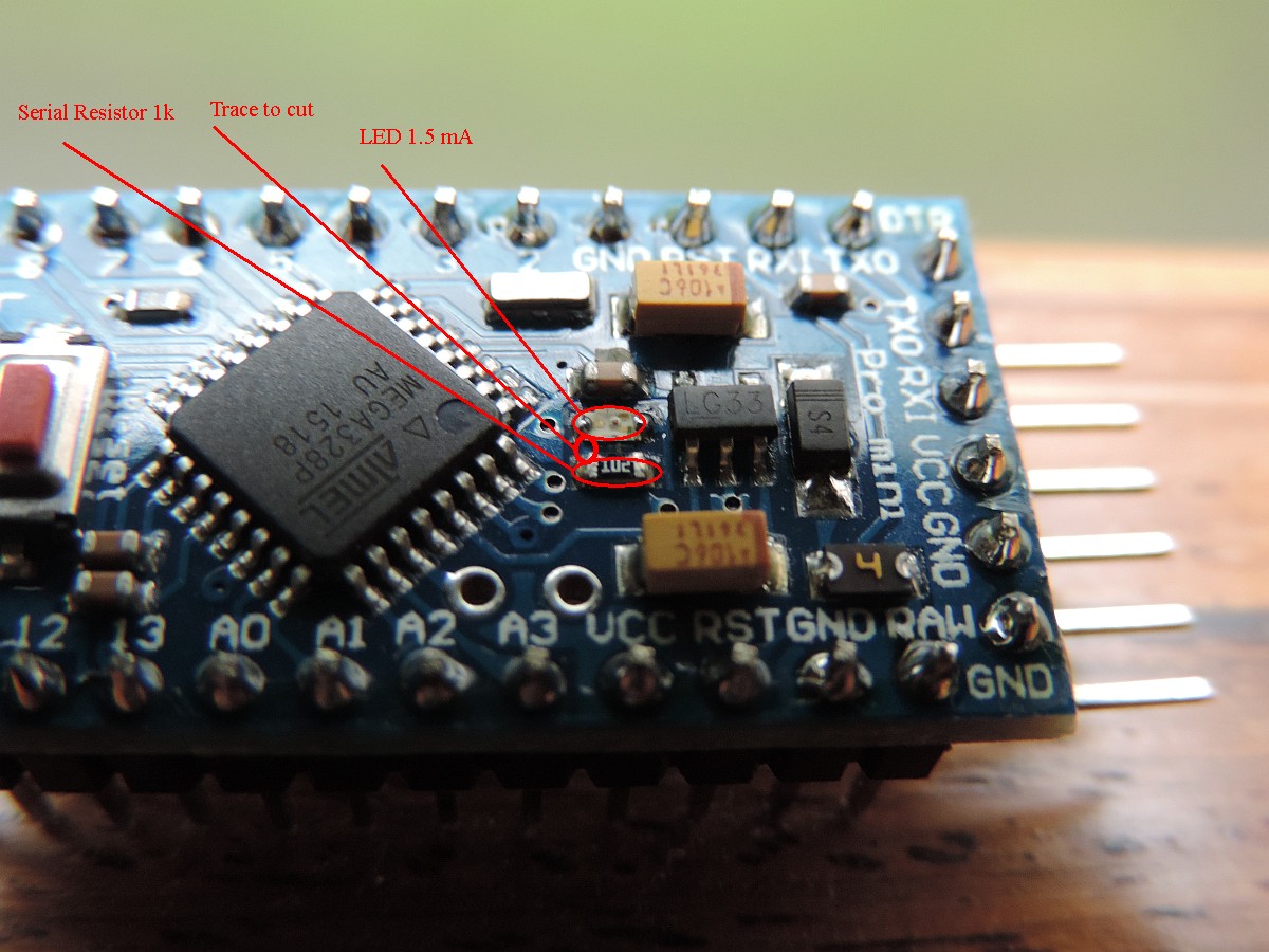
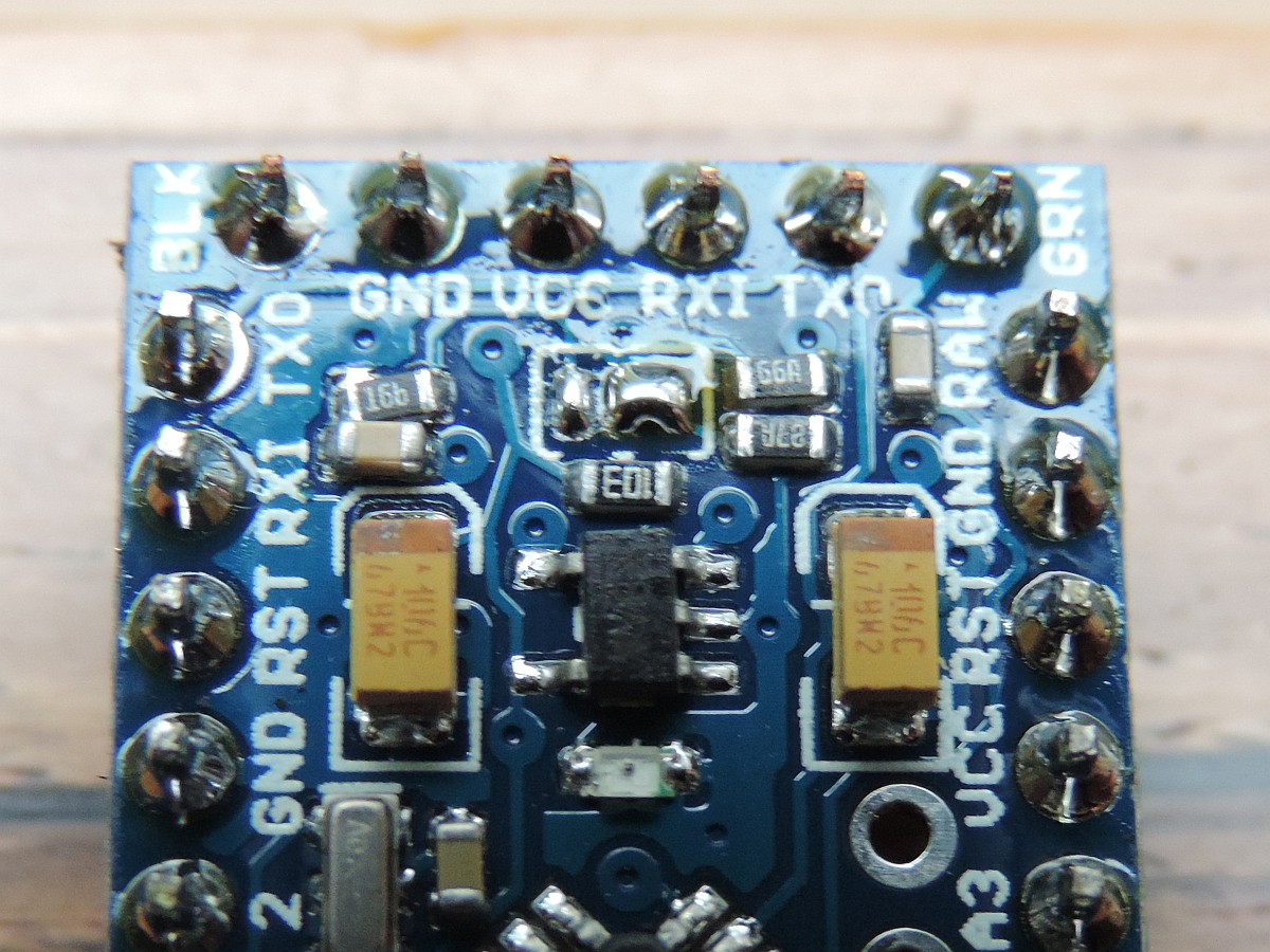
The Arduino Pro Mini operating at 3.3V and 8 MHz has capabilities to operate on batteries as it is possible to put it to sleep/standby between sensor readings. A normal Arduino Pro Mini running continuously together with a DS18B20 sensor and a 433MHz transmitter consumes about 2800 uA. (2.8 mA). When in idle mode, it is possible to reduce the power of the Arduino Pro-Mini to about 2,500 uA (on my meter). By disabling the LED we can cut power with another 2,4 mA and we see our power usage reduced to 70 uA (!!!). The LED is connected with a serial resistor of about 1kOhm which explains the power usage by the LED. Please find below (and lick to enlarge) an picture of the Arduino Pro-Mini and what trace to cut to disable the LED.
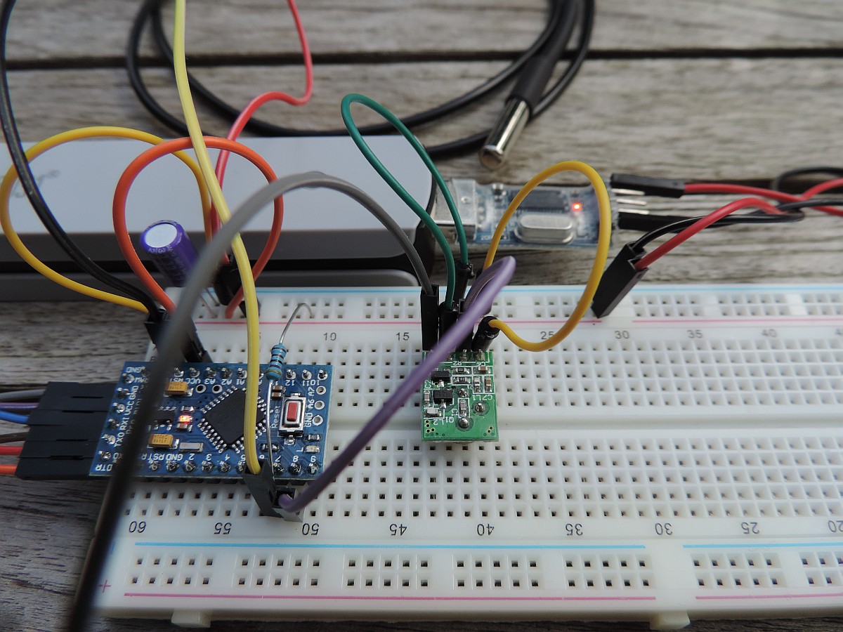
So it seems we achieved our goal here: Very low power consumption during the 1 minute wait time between sensor readings and accept a short burst of power when the sensor is active and the transmitter activity shortly after that. However, the total hi-power time is probable in the order of 0.5-1.0 seconds every minute.
 |
|---|
The Arduino Pro Mini working on Battery power. The 6-pin FTDI connector left is connected to the board but not to the FTDI interface. |
Of course it is possible to further cut-down on power usage. For example by disabling the power regulator on board of the Arduino. However, I have trouble finding the small traces on the board and will only do this when absolutely necessary (afraid of destroying by board).
Measuring the remaining battery power is is a very useful thing for battery operated sensors. So if the battery level drops below a certain value (say 1.1 Volts for a AA Alkaline cell) we see an LED blinking on the sensor board or we receive special battery sensor messages from the sensor (or both).
The Arduino has an internal Analogue-Digital Converter (ADC) on board that can measure a voltage level and return a digital value indicating the level measured. The Arduino ADC has an internal reference value of around 1.1Volts DC, which means that when we measure 1.1V we receive the maximum measured value (and when we measure a voltage level of 0 Vdc this is 0). So for our 3 AA-cell battery which has a voltage of 3 * 1.5 = 4.5 Vdc. Therefore, the max is 4.5Vdc for fresh batteries and below (3 * 1/1 = ) 3.3 Vdc we should rapidly replace the batteries.
The solution is to build a voltage divider with two resistors so that the resulting Voltage at the measuring analog pin will not exceed this 1.1V internal reference value. When we take into account that the input voltage of the battery will be 4.5 Vdc of evel a little higher, the voltage devider resistors will be of value 1.0 M and 330K Ohms.
As said the value we get in return is and integer value between 0 and 1023. So we might convert this back to Voltage by multiplying with 4.45 (This is the input voltage for which the voltage devider more or less provides the reference votage of 1.1 V dc) and then dividing by 1023.
Based on the experience I have with the breadboard version and the low power library (I did try several others as well but this one works OK) it is time to put something together that can be installed anyware in my house as a permanent battery powered sensor. The Arduino Pro Mini board is again different from the other one. Not much, but just enough to have a closer look before cutting traces on the board.
Main difference is that this board can be configured for both 3.3V and 5V operation by connecting 2 of the 3 solder islands. A jumper connection of small switch would have been even more convenient, but probably cost too much.
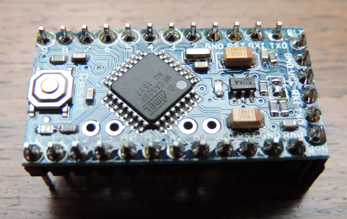
We start with a fresh Arduino, right out of the box, solder the male pin headers (upper and lower row) and solder a female header for the FTDI interface (on the right).
In the picture above you can see the 3 changes to make in order to get the Arduino Pro Mini board ready for 3.3V Battery operation.
Note: The fastest way to get rid of the power regulator is actually a variant on the first "red" change: By not connecting ANY of the three solder islands together, we disconnect the power regulator. We then have to power the Arduino through the VCC pin with the right voltage (2.7 to 4.5 VDc works). The raw pin and the VCC pin on the FTDI header are not usable anymore.
After removing LED and working around the power regulator the board now consumes around 20 uA.
So this is the final resulting battery sensor working on 3x AA size batteries. It will probably last more than a year on one set of batteries and batteries, Arduino Pro Mini, sensor and transmitter will fit in one of my black project boxes. If I want be get the whole thing even smaller, I will have to power on 2 x AA size batteries. This can be done and batteries will last long as well. However, I will have to wait on such battery holder to arrive from eBay berfore I can be sure.

One thing I did not realize before using my first HTU21d sensor is that the Arduino Pro Mini does not output pins A4 and A5 in a simple manner which makes connecting such I2C sensors more difficult. The small connector where the SCL (brown) and SDA (blue) pins are connected to is a simple solution but will make the whole board a little thicker.
As you can see I used the bent pins for attaching the FTDI interface on the left. It is also possible to use female headers (up or down direction) to connect the FTDI interface and this will probably save some space in the final enclosure. And since we aonly need access to this FTDI interface during Arduino programming, accissibility of the pins for occasional use is not so important.
For more information on low-powered (battery) Arduino sensors please visit one of the following links.
The message format of messages exchanged between the Raspberry and the Arduino is defined on the following page(s). As sensors only have an active transmitter to send sensor values to the host, the message format can be very simple. For the moment we use the WT440h protocol (and the variant to code airpressure) as the basis message format.
We do no checking or further processing on the Arduino Sensor side, if we get any reading apart from an obvious error: just transfer the measured values back to the server.
The new green BMP180 and the HTU21D board do have the same pin lay-out. Therefore in principle it is possible to stack the two boards with a little header space in between. This would mean simple wiring and two sensors on one board. The software would be able to deal with this and send two sensor readings with the same address (specified in the .h file at compile time) but with 2